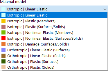
Se l'add-on Analisi del comportamento non lineare del materiale è attivato (licenza necessaria) nel Modello - Dati di base, ci sono ulteriori opzioni per la selezione nell'elenco dei modelli di materiale oltre a 'Isotropo | Linear Elastic' and 'Orthotropic | Linear Elastic' material models.
If you use nonlinear material models in RFEM, an iterative calculation is always performed. Depending on the material model, a different relation between the stresses and strains is defined.
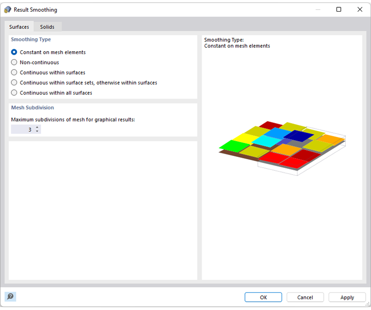
La rigidezza degli elementi finiti viene regolata ancora e ancora nel corso delle iterazioni fino a quando non viene soddisfatta la relazione tensione-deformazione. The adjustment is always carried out for an entire surface or solid element. Therefore, we recommend always using the Constant on mesh elements smoothing type when evaluating stresses.
Some material models in RFEM are indicated by 'Plastic', others by 'Nonlinear Elastic'.
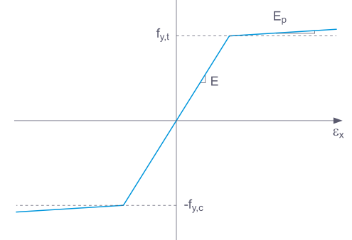
If a structural component with a nonlinear elastic material is released again, the strain goes back on the same path. When completely unloaded, there is no strain left.
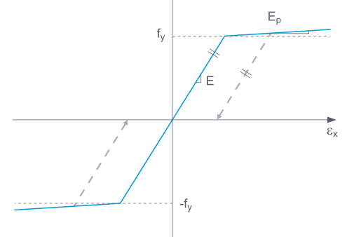
When unloading a structural component with a Plastic material model, the strain remains after it has been completely unloaded.
Background information about nonlinear material models can be found in the technical article describing the Yield laws in isotropic nonlinear elastic material model.
The internal forces and moments in plates with nonlinear material result from the numerical integration of the stresses over the thickness d of the plate. To define the integration method for the thickness, select the Specify integration method option in the 'Edit Thickness' dialog box. The following integration methods are available:
- Quadratura Gauss-Lobatto
- Regola di Cavalieri-Simpson
- Regola del trapezio
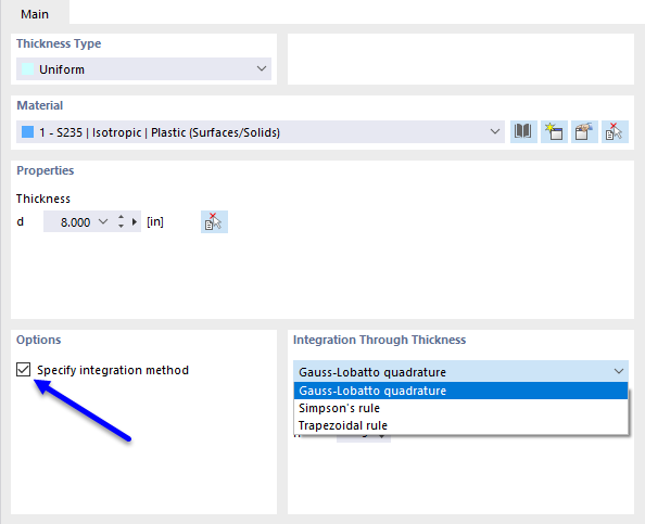
Furthermore, you can specify the 'Number of integration points' from 3 to 99 by the plate thickness.
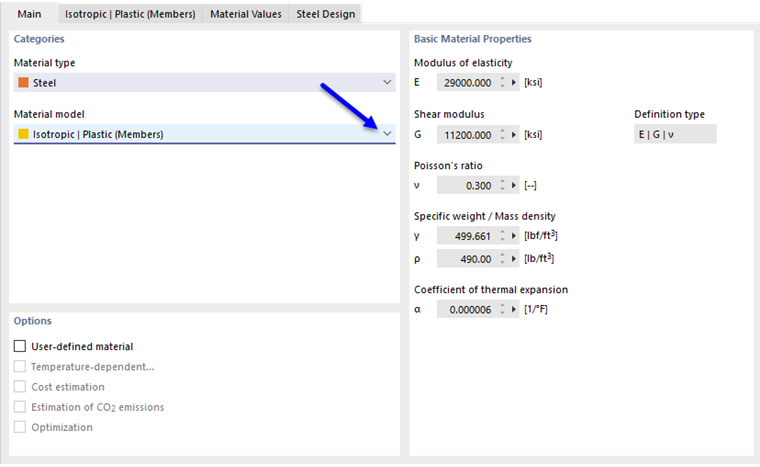
Isotropic Plastic (Members)
When selecting the Isotropic | Plastic (Members) entry in the 'Material model' drop-down list, the tab for entering nonlinear material parameters is enabled.
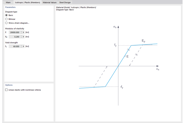
In this tab, you define the stress-strain diagram. Sono disponibili le seguenti opzioni:
- Corso base
- Bilineare
- Diagramma delle tensioni-deformazioni
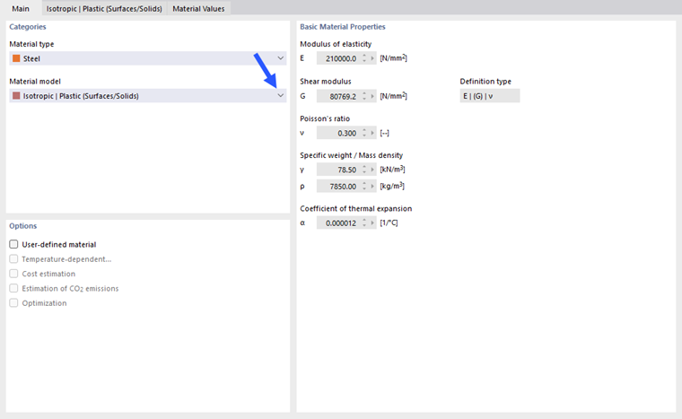
If Basic is selected, RFEM uses a bilinear material model. Values from the material database are used for the modulus of elasticity E and the yield strength fy For numerical reasons, the branch of the graph is not exactly horizontal, but has a small Ep slope.
If you want to change the values for yield strength and modulus of elasticity, activate the "User-defined material" check box in the 'Main' tab.
.png?mw=760&hash=71b7bbc321a70ced69f44a699a9cb56400c9d7bf)
For a bilinear definition, you can also enter a value for Ep.
More complex relations between stress and strain can be defined by means of the "Stress-strain diagram". When selecting this option, the 'Stress-Strain Diagram' tab is displayed.
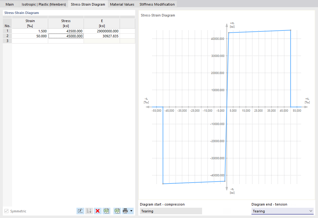
Define a point for the stress-strain relation in each table row. You can select how the diagram continues after the last definition point in the 'Diagram end' list below the diagram:
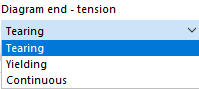
In the case of 'Tearing', stress after the last definition point jumps back to zero. 'Yielding' means that stress remains constant when strain increases. 'Continuous' means that the graph continues with the slope of the last section.
Isotropic Plastic (Surfaces/Solids)
When selecting the "Isotropic | Plastic (Surfaces/Solids)" entry in the 'Material model' drop-down list, the tab for entering nonlinear material parameters is enabled.
Wählen Sie zunächst die 'Spannungsversagenshypothese' aus. Zur Auswahl stehen diese Hypothesen:
First, select the 'Stress failure hypothesis'. The following hypotheses are available for selection:
- von Mises (von Mises yield criterion)
- Tresca (Tresca yield criterion)
- Drucker-Prager
- Mohr-Coulomb
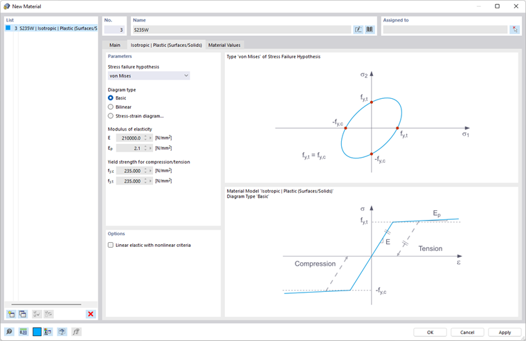
When selecting "von Mises", the following stress is used in the stress-strain diagram:
Superfici:
Solidi:
According to the "Tresca" hypothesis, the following stress is used:
Superfici:
Solidi:
According to the "Drucker-Prager" hypothesis, the following stress is used for surfaces and solids:
| σC | Tensione limite per compressione |
| σt | Limita lo stress per la tensione |
According to the "Mohr-Coulomb" hypothesis, the following stress is used for surfaces and solids:
Isotropic Nonlinear Elastic (Members)
The functionality largely corresponds to that of the isotropic plastic (members) material model. The difference is that no plastic strain remains after the unloading.
Isotropic Nonlinear Elastic (Surfaces/Solids)
The functionality largely corresponds to that of the isotropic plastic (surfaces/solids) material model. The difference is that no plastic strain remains after the unloading.
Isotropic Damage (Surfaces/Solids)
A differenza di altri modelli di materiale, il diagramma tensioni-deformazioni per questo modello di materiale non è antimetrico rispetto all'origine. Thus, the behavior of steel fiber-reinforced concrete can be displayed with this material model, for example. Find detailed information about modeling steel fiber-reinforced concrete in the technical article about Determining the material properties of steel-fiber-reinforced concrete.
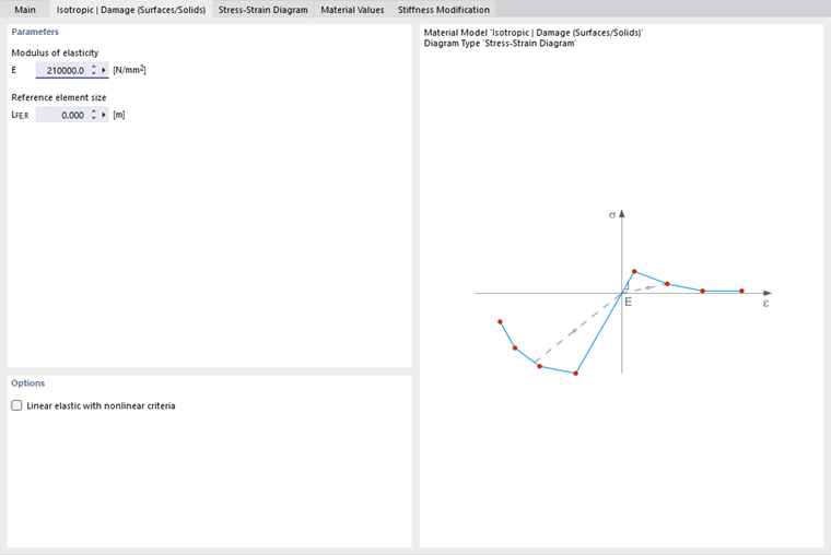
In questo modello di materiale, la rigidezza isotropa è ridotta con un parametro di danno scalare. Questo parametro di danno è determinato dalla curva di tensione definita nel diagramma. This does not take the direction of the principal stresses into account; rather, the damage occurs in the direction of the equivalent strain, which also covers the third direction perpendicular to the plane. The tension and compression area of the stress tensor is treated separately. Different damage parameters apply in each case.
The "Reference element size" controls how the strain in the crack area is scaled to the length of the element. With the default value zero, no scaling is performed. Thus, the material behavior of the steel fiber concrete is modeled realistically.
Find more information about the theoretical background of the 'Isotropic Damage' material model in the technical article describing the [https://www.dlubal.com/en/support-and-learning/support/knowledge-base/001461 Nonlinear Material Model Damage.
Orthotropic Plastic (Surfaces) / Orthotropic Plastic (Solids)
The material model according to "Tsai-Wu" unifies plastic with orthotropic properties. This allows for special modeling of materials with anisotropic characteristics, such as fiber-reinforced plastics or timber.
If the material is plastified, the stresses remain constant. The redistribution is carried out according to the stiffnesses available in the individual directions.
BILD
BILD
The elastic area corresponds to the Orthotropic material model. The following yielding condition according to Tsai-Wu applies to the plastic zone:
Surfaces (2D):
FORMEL
Solids (3D):
FORMEL
Tutte le resistenze devono essere definite positivamente.
You can think of the stress criterion as an elliptical surface in a six-dimensional stress space. If one of the three stress components is applied as a constant value, the surface can be projected onto a three-dimensional stress space.
If the value for fy(σ) according to the Tsai-Wu equation, plane stress condition, is smaller than 1, the stresses are in the elastic zone. The plastic zone is reached as soon as fy(σ) = 1. Values higher than 1 are not allowed. The model behavior is ideal-plastic, which means there is no stiffening.